

Tail Rotor
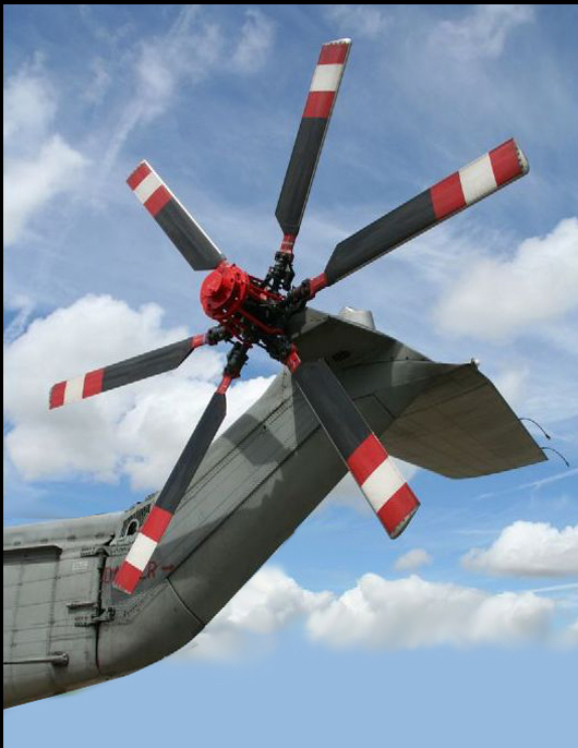
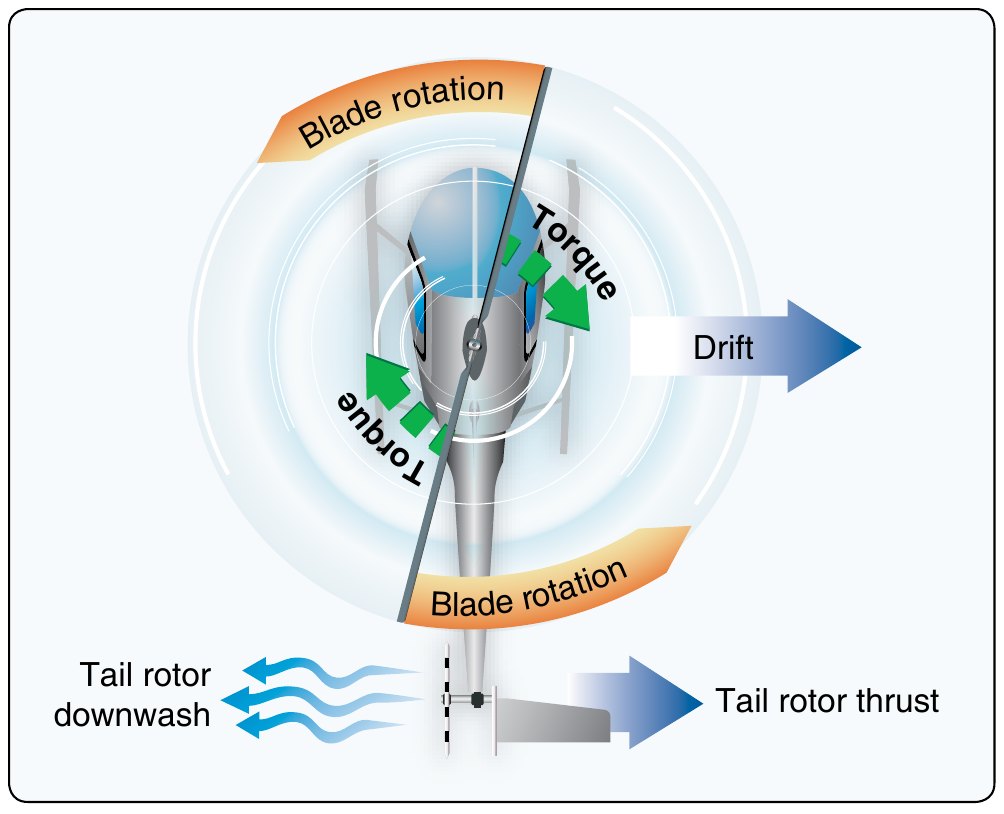
A small, high-RPM propeller-like rotor mounted at the tail. Two jobs: counteract main rotor torque (so the fuselage doesn't spin in the opposite direction of the main rotor) and provide yaw control via the anti-torque pedals. The tail rotor consumes 5-15% of engine power even in straight-and-level flight, and its degraded performance under certain wind/airspeed combinations is the cause of Loss of Tail Rotor Effectiveness.
Pedal sense — US (CCW main rotor)
For most US-built helicopters with a main rotor turning counter-clockwise as viewed from above, the standard pedal sense is:
- Right pedal reduces the thrust the tail rotor is producing, so less is opposing the fuselage's natural rightward torque and it turns the nose right. Net effect: right pedal yaws the nose right.
- Left pedal = increases tail rotor leftward thrust = overcomes torque and yaws the nose left.
The simple way to remember: pedals work like rudder pedals. Push left, nose goes left. Push right, nose goes right. The mechanism is different (changing tail rotor pitch rather than deflecting an aerodynamic surface) but the effect is the same.
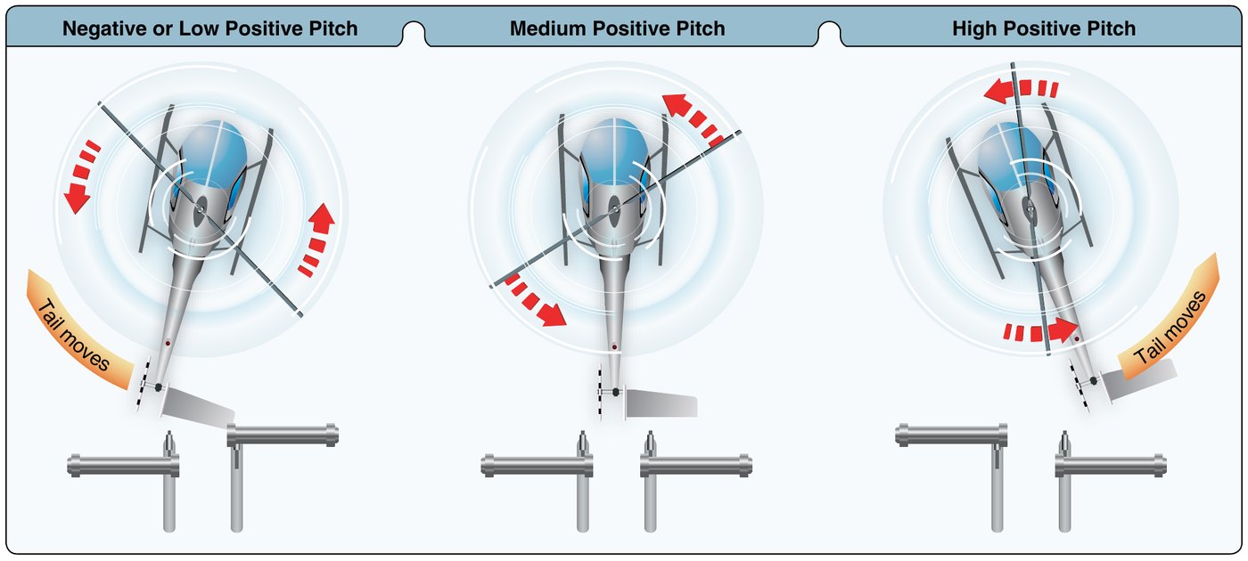
For European helicopters with a clockwise main rotor (Eurocopter family, MBB), the pedal sense is the same — push left, nose left — but the underlying torque and tail rotor thrust directions are reversed.
Why the tail rotor is so often a problem
The tail rotor is a small disc operating in the rotor wake of the main rotor, near the tail boom (which disrupts its airflow), at high RPM, and producing lateral thrust that's strongly affected by relative wind direction. Several failure modes are unique to it:
- Loss of Tail Rotor Effectiveness (LTE) — aerodynamic, not mechanical. Wind from certain directions degrades thrust. Full discussion.
- Dissymmetry of lift on the tail rotor — the tail rotor has an advancing and retreating side, just like the main rotor, and produces uneven thrust as the helicopter sideslips or yaws. The figure below shows the asymmetric thrust distribution.
- Tail rotor vortex ring state — the tail rotor descends into its own thrust column under certain wind conditions.
- Drive failure — drive shaft, gearbox, or coupling. Mechanical, not aerodynamic. Recovery: autorotation.
- Blade strike — the tail rotor is close to the ground when the helicopter is on a slope or in tall grass. Strike damage can be catastrophic.
Anti-torque alternatives
Not every helicopter has a conventional tail rotor:
- NOTAR (No Tail Rotor) — MD Helicopters' system. Compressed air ducted through slots in the tail boom uses the Coanda effect plus a directable jet at the end. No exposed tail rotor blades — safer for ground operations.
- Fenestron — a shrouded tail fan with multiple blades inside a duct. Eurocopter signature. Quieter, less hazardous to bystanders, but power-hungry.
- Tandem rotor — Chinook (CH-47). Two counter-rotating main rotors cancel each other's torque. No tail rotor at all. Used on heavy-lift designs.
- Coaxial rotor — Kamov family, some new civilian designs. Two counter-rotating main rotors on the same mast. Same torque-cancellation principle as tandem.
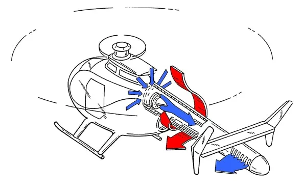
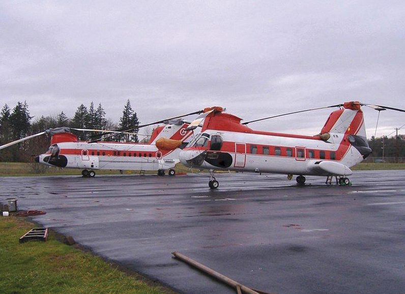
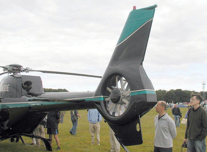
All four solve the same fundamental problem (canceling main rotor torque) with different mechanical approaches. Aerodynamic principles around torque and LTE-equivalent failure modes apply differently to each.
Pre-flight tail rotor check
- Tail rotor blades — visual inspection for damage, leading-edge erosion, nicks, delamination.
- Pitch-change linkages — full freedom of movement, no binding.
- Tail rotor gearbox — oil level, no leakage.
- Hanger bearings (if applicable) — inspect each per POH guidance.
- Drive shaft couplings — secure, no excessive play.
- Tail rotor guard / fin — undamaged, secure.
The tail rotor is one of the highest-stress parts of the aircraft and one of the easiest to damage on the ground (low to the ground, often near vegetation or obstacles). Walk back and look at it carefully on every preflight.